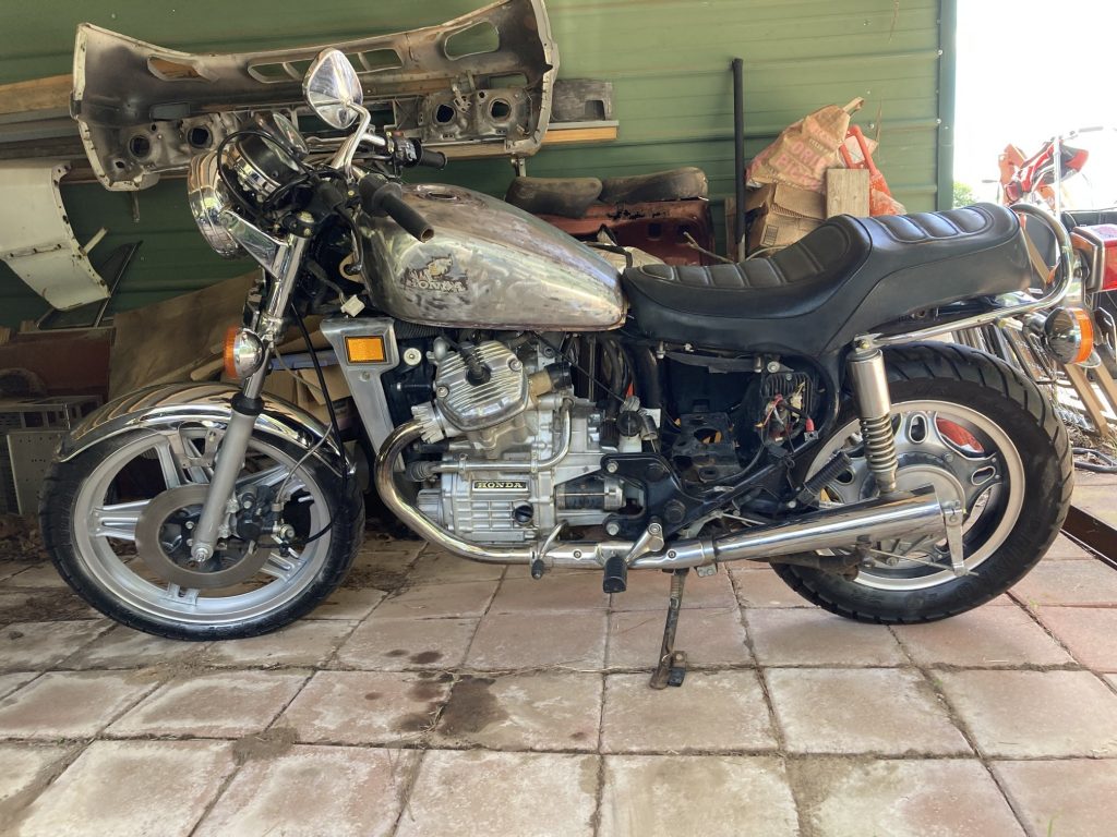
The Honda CX500 motorcycle has been on my Build Bucket List for a while now. I ran across pics of CX500’s in cafe and brat formats often when searching for ideas on the Iron Krush and the Caliber 90 bikes, and I really was interested in eventually building one. This one came along unexpectedly and for a reasonable price, so I scooped it up for a someday/maybe project.
Initial form of the bike
Of course someday/maybe means NOW when something is new to you, so the bike has already had a bit of work done on it. The goal is a basic, ride-able, cafe / brat appearing bike, but nothing over the top, or over expensive.
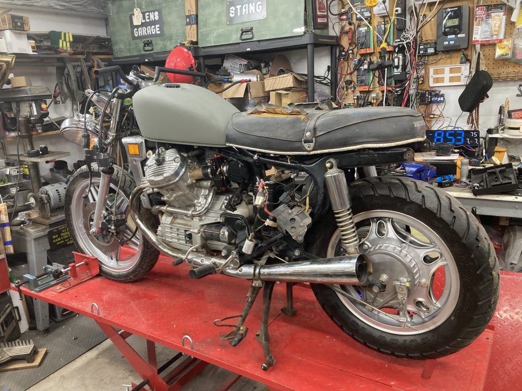
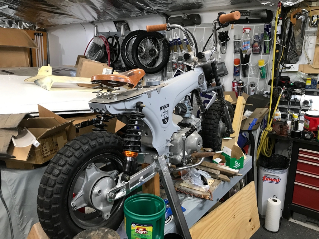
On the lift with some things done
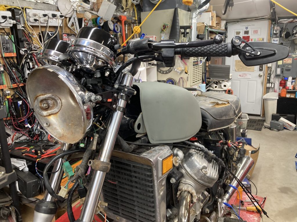
The mindset behind the build is a rather mild cafe / brat style of bike. Although clip on or low mount handle bars do make it look cooler, the ride-ability drops a lot in my opinion. Some low riser bars were used to keep the rider profile a bit more comfortable. The original handle bar controls were maintained after cleaning up and refurbishing. The original speedometer and tach were also kept, but the mount was bent down to flatten the gauges out a bit and make them more visually appealing.
Low profile bars, stock speedo and tach leveled out, aluminum headlight mounts and end mount mirrors
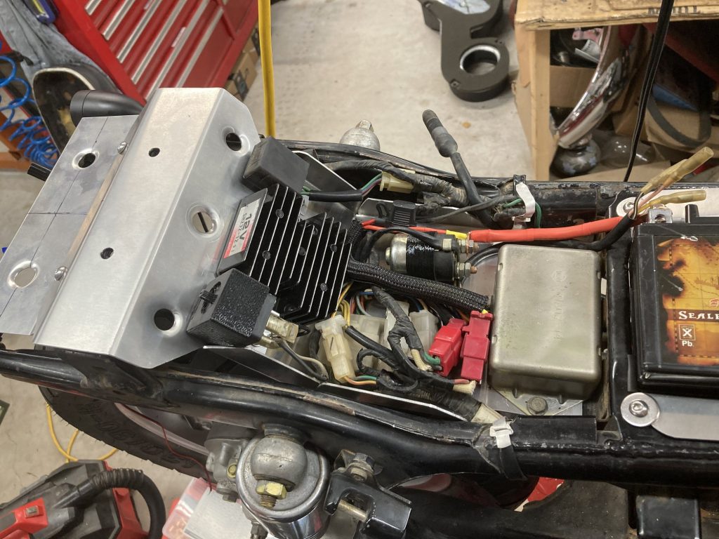
Although initially I had planned on leaving the battery mounted in the old air box location, after some thought I ended up building my own battery and electronics mounts to get everything located under the seat opening up the battery and air box area.
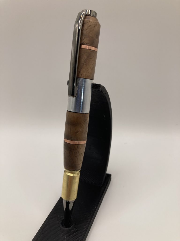
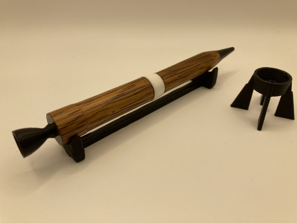
Sided tracked by my cousin in early September 2024, I’ve taken a liking to turning small wood projects such as pens, bowls, bottle stoppers, openers, and even mice. Fun and something new to learn.
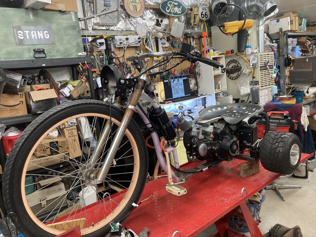
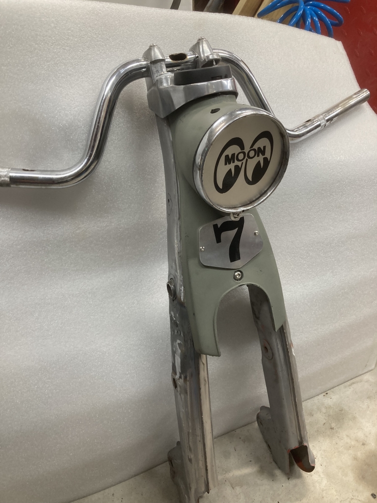
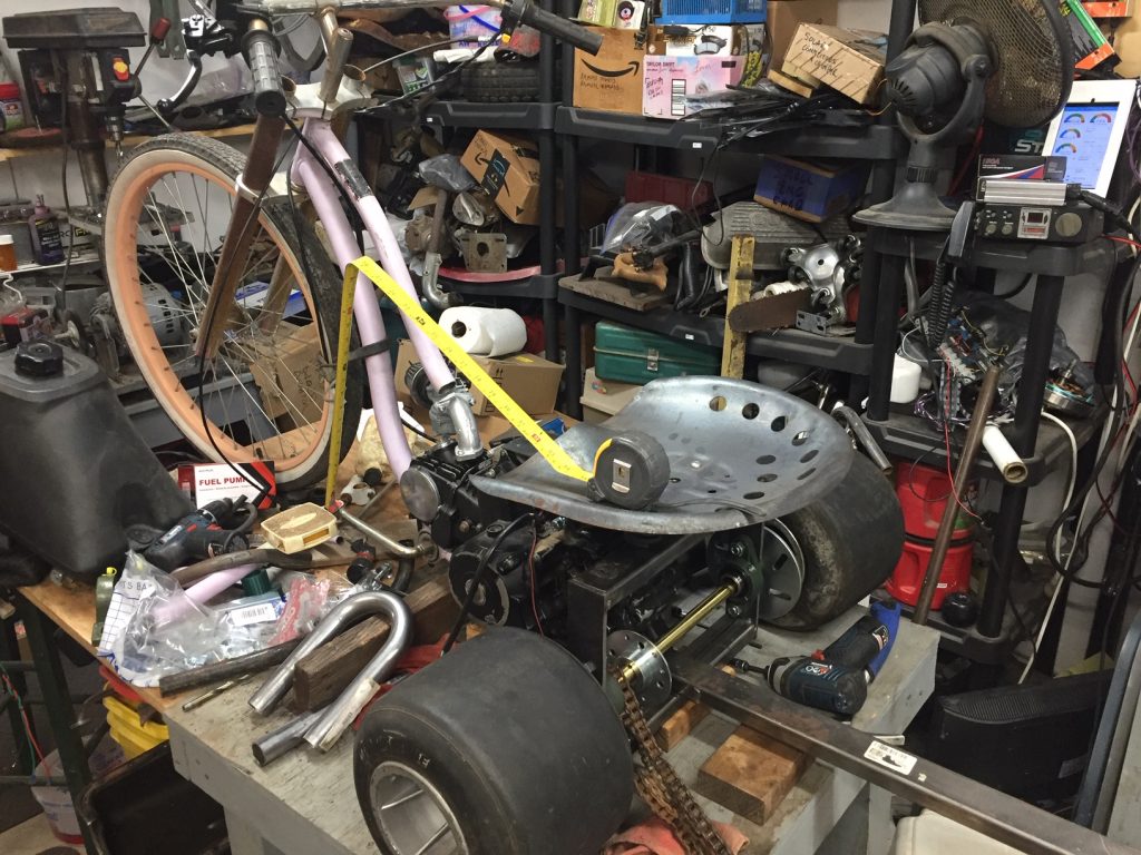
Progress on the Mustengo Drift(ish) trike this month. This project has been sitting for some time, but after rearranging the shop and getting it on the lift, it’s time to get it finalized.
Yet another motorcycle project is in the house. The “Iron Krush” CT70 is done as well as the “Caliber 90” (Updates to the pages coming soon), but this one followed me home and the idea is there on how to build this rescue.
Finally getting back to this neglected CT 70 Mod project. It’s pretty much laid out, so now it’s blown apart for prep and paint and some details before final assemble.
Gasification? Personally I had never heard of it until recently. Could be quite an interesting project, especially in today’s times… Robert Murray-Smith does a pretty good job of explaining his build below.
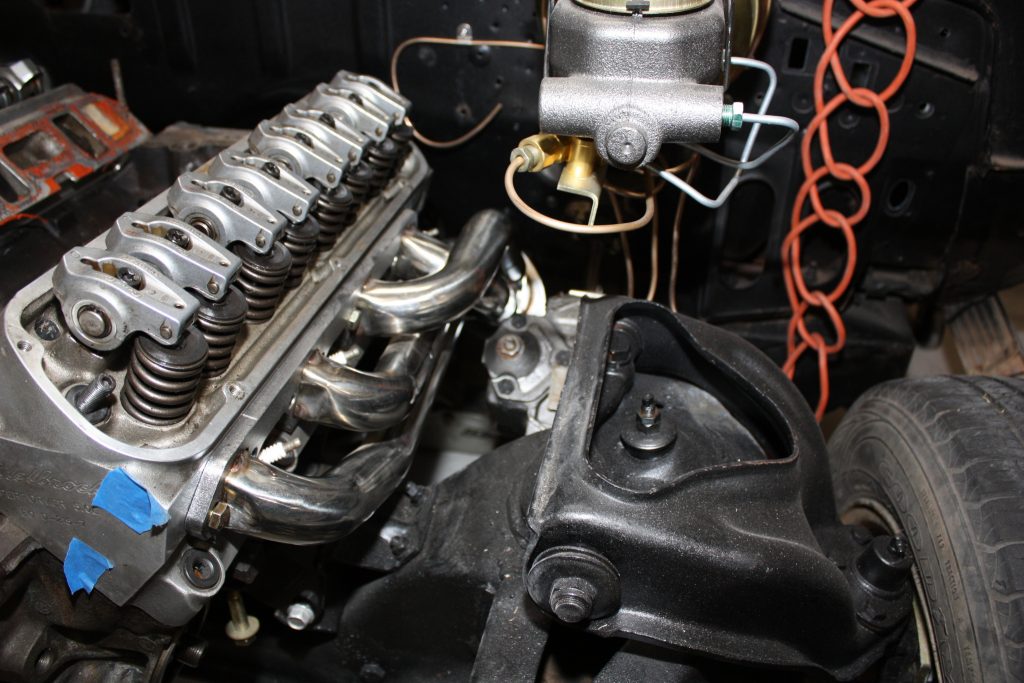
I obviously bounce between project to project, hobby to hobby, and wander around between other interests. Personally, I’m good with that, as I enjoy every day I have on this planet to do those things. My latest wander is back to the ’66 Galaxie.
This was partly driven by finally moving my toolbox from the garage to the shop and putting it where the engine stand was for this block, heads, etc, but also driven by the need to get the Galaxie moving along this year.
I was at the point that I needed to get something in the car to check some fitments, work out the hold location for the shifter, and finalize the hydraulic clutch setup, so an empty block and the recently cleaned up WC T5 were dropped into the car for now.
I’ve had RGB light strings running around the house integrated into Home Assistant and stand alone for a few years, but they all ran my own code. That’s good and bad. The good is I can add whatever effects and control I like, the bad is I’m not very good at creating effects so I just use what’s out there. The other bad is how the lights start up and some bugs in my code that are hard to track down. Enter WLED…
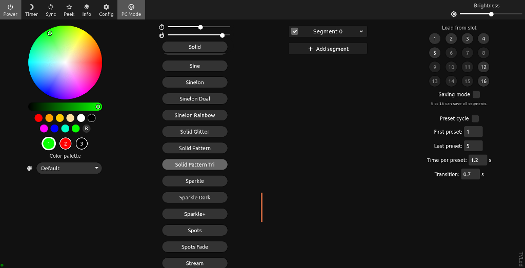
WLED Interface in PC Mode
Dee, a friend of mine was wanting to do his own holiday lights and told me about WLED, an open source ESP8266 based RGB or RGBW package, that is easy to setup, easy to use, and easy to control effects via an http API. The only down side was initially I didn’t know how to API worked and was kind of stuck with using only the web interface to setup schedules, etc.
However, once I dug into the http API, I could see how I could more easily control the lighting and scheduling from my own methods. In my case, this is via a PHP page that gets called at sunset, but it could easily be a Python script or anything else that can be run to make calls to the API.
The WLED interface is actually quite good allowing color, effects, effect cycling, and favorite setups to be saved. In PC Mode like above, one can get to the core controls, in normal mode one can get to all the menus, including WiFi, LED, syncs, user settings, time, etc.
Once the various locations were installed including the front door, portal window, under the eave run, and a couple inside strands or strings, I moved to getting things setup to allow custom effects, colors, etc for holidays, or just a low key spot light effect for all other times.
I have Home Assistant make a call to my PHP code at sunset every night. This allows lights to come on at the appropriate time each day. Again, this code is in PHP, but Python could be used just as easily. A lot of this could also be done in Home Assistant I’m sure, BUT I liked my freedom to code in PHP or other languages.
First I need to explain the postWLED function. I initially was using the normal PHP get_file_contents() function but having huge delays making the WLED calls. No clue why, but decided to use the curl function instead which solved the problem. Not sure why yet but this works so I’m sticking to it. The function just sets up and calls curl to do the http request. In Python the “requests” library should work fine.
// postWLED uses curl to post to WLED - the get_file_contents() function hangs trying to hit the URL but this fails quickly if a device isn't online
function postWLED($myValue)
{
	$url = $myValue;
	$client = curl_init($url);
	curl_setopt($client,CURLOPT_RETURNTRANSFER,true);
	$response = curl_exec($client);
	echo "<BR><a href=$myValue target=_blank>$myValue</a>";
	echo "<BR>$response";
	return $response;
}
In the main code, first I pull the month and day so I can check for any applicable holidays. Next I reset all the strands to preset 16 (&PL=16) and turn of any preset cycle settings (&CY=0). This is the default setting for each string or strand.
// Handle WLED settings for holidays as desired
$curMonth = date('m');
$curDay = date('d');

$HolidayMode = false;

// Reset everything to default 16 values
echo "<br>Setting NON Holiday Mode";
postWLED("http://192.168.xxx.75/win&CY=0&PL=16");
postWLED("http://192.168.xxx.76/win&CY=0&PL=16");
postWLED("http://192.168.xxx.77/win&CY=0&PL=16");
postWLED("http://192.168.xxx.78/win&CY=0&PL=16");
postWLED("http://192.168.xxx.79/win&CY=0&PL=16");
Next are the date comparisons to see what effects or colors we’d like to display. Currently this is done via simple day checks. Next we make the calls to the end points to handle the settings as desired. Below this would come on the 13th and 14th of February each year. One could also use the .local domain option to make the calls such as http://front_holiday_lights.local/win instead if you set the nDNS up under the WiFi settings page. I started out using IPs but could change it when desired. The IP assignments are .75 as the portal but it slaves off the front door of .76, .77 is TV back lighting, .78 is main front eaves, and .79 are the living room string.
// Valentines day
if (($curMonth == 2) AND (($curDay == 13) OR ($curDay == 14)))
{
  postWLED("http://192.168.xxx.77/win&CY=0&FX=88&R=255&G=0&B=0&R2=255&G2=255&B2=255");
  postWLED("http://192.168.xxx.78/win&CY=0&FX=88&R=255&G=0&B=0&R2=255&G2=255&B2=255");
  postWLED("http://192.168.xxx.79/win&CY=0&FX=88&R=255&G=0&B=0&R2=255&G2=255&B2=255");
  $HolidayMode = true;
  $myText = "New Years WLED Settings Applied";
  putHassio("notify.sendgmail",$myText);

}
In the case above, I turn off the preset cycle (&CY=0), set the effect to “Candle” (&FX=88), set the primary color to red and the secondary color to white. A list of all the effects for API calls is documented her (https://github.com/Aircoookie/WLED/wiki/List-of-effects-and-palettes)
For Christmas lights, the time period is obviously longer, and the approach slightly different. With the 16 favorite save options, I use #16 as the default, but have dedicated #12-#15 for Christmas effects that then get cycled through by turning on the preset cycle option (&CY=1). Below is the Christmas light time period. Note the front door (.76) has a shorter cycle. It also has a different effect cycle in the 12-15 favorites. The TV goes to a standard red one side, green the other side to avoid annoying effects behind the TV, and the inside and outside run a 12-15 cycle that are unique to their own settings. Below the Christmas lights run from 11/25 through 12/27.
// Christmas lights starting around Thanksgiving
if (($curMonth == 11) AND ($curDay > 25) OR (($curMonth ==12) AND ($curDay < 27)))
{
  echo "<br>Setting Christmas Mode!";
  postWLED("http://192.168.xxx.76/win&CY=1&P1=12&P2=15&PT=6000");
  postWLED("http://192.168.xxx.77/win&CY=0&PL=12&CY=0");
  postWLED("http://192.168.xxx.78/win&CY=1&P1=12&P2=15&PT=60000");
  postWLED("http://192.168.xxx.79/win&CY=1&P1=12&P2=15&PT=60000");
  $HolidayMode = true;
}
The $HolidayMode variable isn’t used yet, but can be used after the date checks to do some other functions if the lights are in holiday mode, such as turn off the porch light to allow better holiday light viewing.