n.
A very small person or being.
adj.
1. Very small; diminutive.
2. Trivial; petty.
January 2014
Lilliputian – seems like a pretty good description of this little fellow. Trivial, petty, diminutive, very small, etc. With all due respect to Swift’s Gulliver’s Travels of course. Inspired by Yahmez MicRObot challenge, this is my 2.0 attempt. The first attempt is still there and maybe viable for a future finish but I like this 2.0 layout much better. I just packed in as much as I could WITHOUT resorting to surface mount devices (SMD) which I have no skills with.
Size Matters
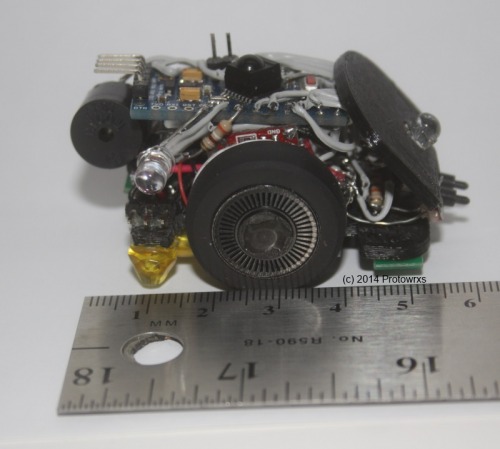
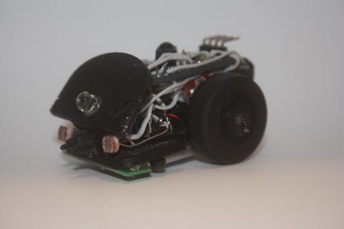
At least in the challenge so first I guess I should outline the current size of Lilliputian. Currently the bot is about 35mm wide by 50mm long (not including the bumper horns) and 35mm tall. Total weight is 34 grams (1.2 oz). Not tiny by any means or as compared to some other entries I guess but small for me. I gave up some size for features which was the plan from the beginning.
Chassis and Motors
Lilliputian features a 3D printed base chassis of my own simple design to mount the two GM15 micro motors. To keep things narrow I offset the motors and wheels giving it a bit of a goofy stance but making it much narrower than traditional back to back mounting. That is where some 90 degree gear motors such as those recently sourced by Yahmez would be quite handy. For wheels, I used a couple old mouse wheels that I had kept. It took a bit of work to clean out the middle to allow mounting and they are definitely crooked and poorly mounted but they have stayed on so far.
For speed control a L293D chip was used and was soldered up “dead bug” style. Without an inverter it does eat up six output pins to control the two motors but I figured I had plenty of pins in this situation. Two pins are used to control motor direction for each side and a pin is then used to drive PWM for each side.
However, the GM15 motors are really geared a LOT higher than I thought there were and the tall mouse wheels really push the speed of the bot beyond usable levels. The balance between enough PWM to move and too much while cruising is a challenge. Some better coding would be helpful as Yahmez suggested to maybe ramp up the power to get rolling and then settling it down for cruising speed. Something to work on later I guess.
I designed the chassis to use basic Pololu QTR encoders with striped disk on the wheels. I’ve done this before with larger sensors but not this small. I thought the Pololu QTR-RC sensors would work as they are small and since I didn’t read the datasheet like a fool I put the thing together and could not get output from the sensor. More reading revealed that you need to use the library to read the sensor as what makes them digital is the small cap that must be charged and then read using the same I/O pin. That will NOT work with driving an interrupt pin for encoder reading. I even tried making my own timer interrupt routine to go read the sensors but could not get any consistent output. Since then I have purchased the QTR-A sensors which are pure analog but have not tested if they can transition enough to drive a digital interrupt pin. Plus the fact that the wheels are glued to the output shafts and the wiring is on the opposite side there is no clean way to replace the existing encoders so that part of the bot is on hold.
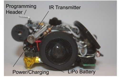
Power
Powerwise a 3.7v lipo with onboard electronics for under / over voltage protection was mounted on the bottom side. It’s easy to get to and replace in case it bloats from overcharging and tucked up underneath quite nicely. However, everything on the bot is 5v so I used a Pololu step up / down regulator to turn the 3.xV into 5V. I believe the current limits are 500ma but it appears to be fine for my needs. Pretty sure I could not have run a ping sensor along with everything off that current but this thing is too small for such a sensor anyhow. I couldn’t find a switch that was small enough in my junk pile so I just used a three pin header for power and changing needs. I use a header jumper to power it up and a three pin connector for the charger. I used a wall wart charger that came with a little quad rotor and it appears to have some current limiting in it as well and has charged the battery without issues. The battery is a 240mah LiPo version but driving the speaker appears to really eat up power so run time is not impressive. Fun, just not impressive.
Brain Power
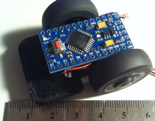
Originally I really thought I would go with one or more ATiny85 CPUs for this build but seeing the ability to mount up a ProMini 328 I changed direction as it is still my favorite Arduino CPU to use since it’s so small with full 328 capabilities and memory all in a 24 pin DIP. Instead of building a undershield or perfboard this time, I simply glued the CPU to another little mount I designed and printed that also mounted the wheel encoders (that do not work as noted above). I then soldered wires directly to the CPU instead of using header pins. Messy but seems best at this scale for me.
Sensors and Stuff
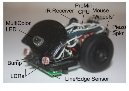
IR Receiver
I added an IR receiver to allow controlling the bot and his “modes” with a standard remote control. Each mode can be selected from the remote including RC control, autonomous mode, and some special entertainment type of functions. The IR sensor mounted on top of the AtMega chip on the ProMini quite nicely in my opinion. For now I’ve used an existing remote from a Toshiba stand alone DVD burner I had in the workspace but any remote could be used as it is quite easy to add IR control to a bot. I used to think that would be a challenge but with the IR library it’s very simple.
The remote is primarily used to change the “modes” of the robot from roam, light seek/avoid, light track/hide, “wag”, bark/attack, line follow, etc. It can also be used to drive the robot around with the arrow and navi buttons if desired.
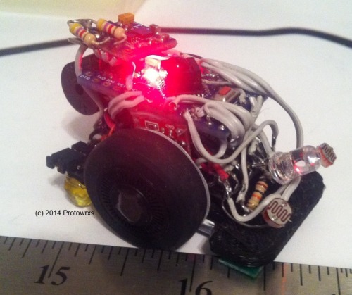
IR Transmitter
Since I could not get the encoders to work, that freed up pin 3 that is used for the IR transmitter library so I stuck an IR emitter on the right rear of the bot. Thoughts are he can eventually communicate with SBot or something like that. Nothing is coded yet but maybe later.
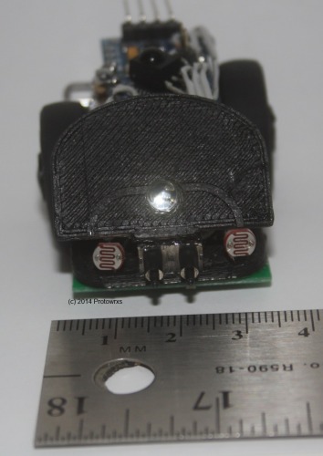
LDR Light Sensors
Sensors are rather simple with two LDR’s for light measurements. Good news is the LDRs work well. Lilliputian can sit still and track light, turn away from light, and follow or run away from light. He also makes little bleepy sounds when he’s not happy with the light balance as he sees it. Bad news is my light follow code isn’t overly developed so he can get confused and start spinning in place rather easily.
QTR-RC Line Sensors
The line sensors do seem to work well using the Pololu library and can easily detect light, dark, and edges. BUT doing so in a fast enough manner to get a timely response from the platform has been a bit of a challenge so far. Additionally my chassis design leaves some to be desired as the offset wheels make it quite easy for the bot to do a “wheelie” when taking off which confuses the front mounted line sensors into thinking it has seen an edge so it stops, backs up, takes off and repeats the loop. Not good. I ended up mounting a small piece of Lego jewel in the back corner to stop the wheelies helping the edge detectors to function.
Bump Sensors
Without sonar Lilliputian is pretty blind so I added a small bump switch up front. I can’t remember where these little switches were scavenged from but they are pretty handy little things that take very little pressure to turn on making them good sensors for a small bot. I think they were out of some old tape backup drives or something. Without whiskers they are pretty limited but does give some sensing to back off, turn and continue on at least.
Light and Sound
I always like my bots to make a bit of light and noise since I’m easily bored so a piezo speaker was salvaged from an old PC motherboard as recommended in the shoutbox and mounted on the rear. A cycling multi-color LED was mounted up front that adds a LOT of colorful light, in fact a bit too much so I added code to turn it on/off via the remote control. With the little speaker Lilliputian can play a few songs and act out or dance a bit.
Feature Set
Lilliputian currently has the following modes and features:
Roam mode
Not overly useful but wanders around bouncing off things, avoids black lines if the line/edge avoid flag is set. Line/edge can be turned on/off with the remote as needed.
Light Track mode
In light track mode Lilliputian sits still and turns toward the brightest light source he can see at the time. If it’s too bright or you get too close to him with a flashlight he will back away from the bright light making a little noise. Again, in this mode he doesn’t drive anywhere forward for light, just sits there.
Light Hide mode
Just the normal inverted light seek mode but again sitting still and turn away from any light source until he is happily balanced. This really doesn’t mean find the darkest point, just turn away from any brighter light source.
Light Seek mode
In light seek mode, Lilliputian follow the brightest light using the front LDRs for balancing. This works best when pointing a flashlight at the front allowing light control of Lilliputian. He will follow the brightest source he sees and once things are bright enough he will stop. If you make things too bright he will back away from the light.
Light Avoid mode
Again standard light avoidance routines, run away from the light. In this mode if he finds a dark enough situation he will stop as well and wait for any light changes.
Race mode
Just a silly little setup where he counts down with blips and takes off at full speed for a second or two. Just like in real racing, sometimes he crashes trying to go too fast. Once done he sings a little tune and spins in place having enjoyed the thrill.
Wag mode
Another silly one borrowed from SBot. Just wags back and forth for you.
Bark / Attack mode
Another silly little routine from SBot where he drives forward, makes a barking/noise sound and retreats.
Line Following mode
Lilliputian is really not well versed in line following yet. He can “usually” follow the line but with the high speed, bad code, and having to check for IR inputs, etc he can easily miss the line and take off running away. Even when following the line he is pretty jerky bouncing around trying to stay on course. But he can make it around a normal line sometimes.
HokeyPokey mode
Apparently he learned this routine from my TED robot I guess. One of the most important routines he plays the song and does the moves the best he can. Seems like he is having fun at least.
Future Feature Set
Maze solving – Really want to have it run the maze, store path, and re-run it… someday
Things that Didn’t Work
Wheel Encoders
Obviously the wheel encoder setup didn’t work as mentioned above. This may be resolved through a different encoder but that will have to be for another bot someday.
Onboard Compass
Originally I really wanted to drop a small HMC5883L compass module I had on the bot. I tested the module on the bench and it worked pretty well. however, mounting it up on Lilliputian proved to kill the usefulness of it as mounted down by the CPU the compass does not work apparently from the RF interference of the CPU or maybe the magnets of the motors underneath it. I have built a small stand off to allow the compass to work but not really crazy about how it looks so not included here.
Closing Summary
So big plans scaled down for the most part. Original goal was wheel encoders, dead reckoning navigation, compass directional controls, Light sensors, line following, maze solving, IR controller, little monster. Reality is a neat little platform but not all the bells and whistles I originally had desired.
Oh well, one can’t hope for too much out of a Lilliputian unless there are a lot of them right?
No, I’m not building a lot of these things – too small for my patience 🙂
Update 01/02/2014 – Added some early Pics Per Lumi’s request, here are a few early on pics. Unfortuately I didn’t take many in process pics like I should have.
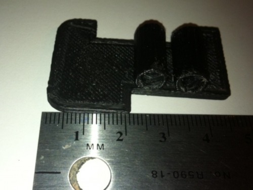
Raw printed chassis that I designed. Very simply base platform and two tubes to hold the motors.
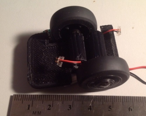
Chassis loaded up with the GM15 motors and mouse wheels/tires.
Mounting the CPU up top. You can’t see the mount which is just a tube with a flat piece on top to mount CPU.
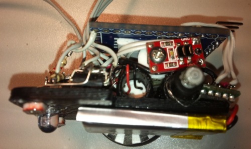
Top view before CPU mount. The step up regulator on the left, H-bridge dead but up front. Initially I was going to try using an LED and a couple LDRs for line follow. Bought sensor instead.
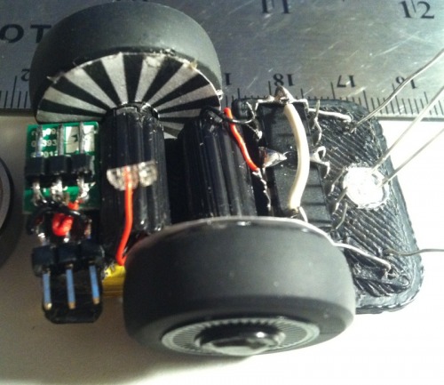
This is the best view I have of the “guts”. Before line sensor install but you can see the wheel encoder attempt. Pretty packed in but generally functional. I still think the right encoders would work. Wouldn’t be high resolution but could be useful.
